
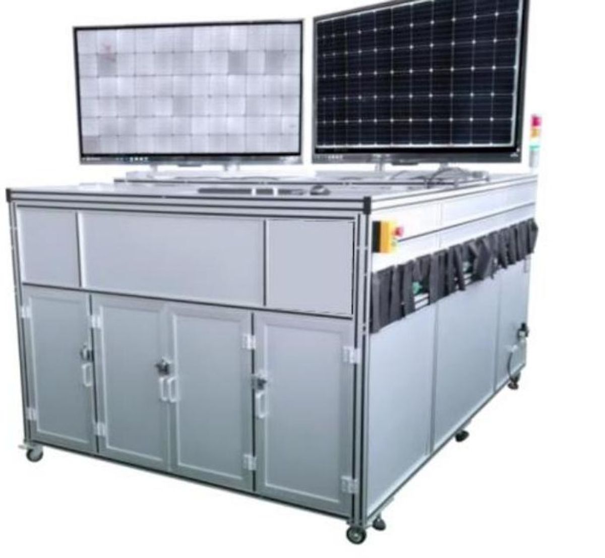
Module inspection is more than single-image classification
Large modules are often imaged using continuous line-scan acquisition rather than captured in one naturally bounded photograph. The workflow must assemble and crop that image before defect analysis begins. Acquisition, image organization, recognition, and production outputs therefore belong to one engineering system. Stability at a single camera or model stage does not establish that the complete inspection path is stable.
Stitch multiple cameras into a valid inspection region
Multi-camera images need a consistent spatial relationship before they can form one inspection surface. Stitching connects the views, while cropping removes borders that do not belong to the product. The resulting valid region shapes both recognition and defect coordinates. Validation should examine seams, boundaries, and product coverage together, because individually acceptable camera views can still produce an unsuitable combined image.
Use models and recipes to manage product changeovers
A product changeover may alter module dimensions, valid regions, and decision requirements. Models identify visual patterns, while recipes organize the regions, rules, and result conventions appropriate to a product. Managing both together prevents an old boundary from being applied automatically to a new format. After changeover, stitching, cropping, model selection, and decision routing should be reviewed as one workflow.
Route defect decisions into alarms, sorting, and records
Defect classes and coordinates become operational only when they reach alarms, sorting, and quality records. Alarms focus attention on exceptions, sorting signals carry a verified disposition, and structured exports such as CSV support aggregation and traceability. These outputs need consistent product and inspection identifiers so engineers can compare the event, production response, and retained record during later review.
Maintain optics, computing, and data for stable operation
Stable operation depends on more than inference software. Lens and illumination conditions determine the incoming image, while industrial computing, disk management, and software backups support processing and record continuity. Maintenance should preserve the image baseline, data availability, and recovery capability. When any of those foundations change, teams need to confirm that current models and recipes still describe the operating condition.
Validation boundaries after production changes
After a production change, thresholds, model versions, filter regions, image retention, and sorting mappings require product- and line-specific validation. Module formats, camera combinations, optics, recipes, and record policies can each change the inspection boundary. Revalidation should cover the stitched region, decision convention, retained evidence, and destination signals rather than assuming that a previous configuration transfers unchanged.