
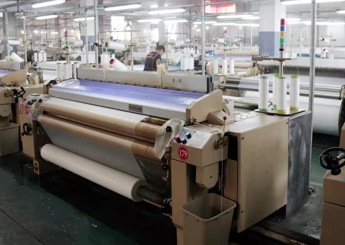
Textile Manufacturing · In-line Vision
Textile Vision Inspection
Switch between fixed line-scan, moving area-camera, and quality traceability options based on loom structure, width, and inspection objective.
- 03
- Inspection stages
- 01
- Related published projects
- 01
- Verified technical document
Production stage
Select imaging by loom structure and web width
Review one stage at a time. The image, published metrics, inspection scope, and project evidence update together.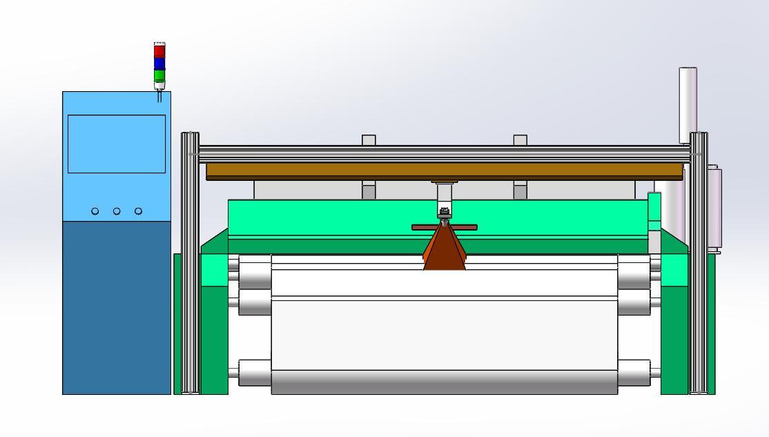
Inspection point · Moving imaging
Area-camera Linear-stage Inspection
One area camera travels on a linear stage for very wide fabric or machine structures that fixed cameras cannot fully cover.
Solution basis
- 1
- Moving camera
- ≤ 6000 mm
- Specified width
- 16/25 mm
- Lens options
- Dual light
- Front / backlight
These are source-defined standard configurations or targets. Final scope is confirmed through sample testing and the technical agreement.
Inspection and integration scope
- 5MP or 2MP area camera
- Front-light and backlight combination
- Site-specific linear-stage travel
- For very wide webs or constrained installation
Featured technical detailIn-line Broken Yarn & Fabric Defect InspectionThe verified broken-yarn solution below includes equipment configuration, site workflow, and software data.Open full detailClose full detail
Overview
Move broken-yarn decisions into weaving instead of downstream inspection
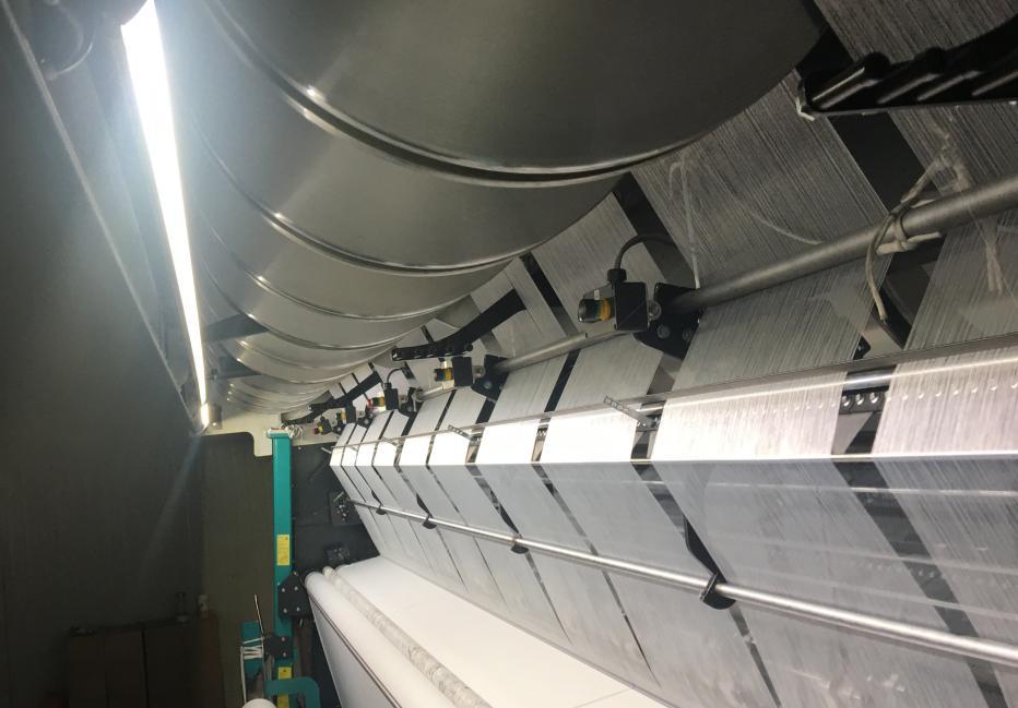
The solution targets warp knitting and other looms, using cameras, lighting, and machine-motion synchronization for continuous acquisition. Broken yarn, oil stains, and other anomalies can be located, alarmed, and recorded as they occur.
Depending on web width and machine structure, the system can use two fixed line-scan cameras or one area camera on a linear stage. Both configurations share defect recognition, statistics, history, and ERP integration capabilities.
Inspection scope
In-line recognition of broken yarn, oil stains, and visible fabric anomalies
Cameras and lighting are arranged around the material surface. Models are refined with labeled site samples to adapt to the defects that matter for each line.
- Broken yarn on warp-knitting and other looms
- Oil stains, contamination, and local fabric anomalies
- Real-time defect image display and positioning
- Statistics by type, position, and time
- Cloud storage with local database backup
- Model refinement after operator review
In-line workflow
A capture, recognition, and feedback loop synchronized with the loom
The system follows machine speed and retains defect images and statistics.- 01Motion sync
An encoder or linear stage coordinates imaging with loom motion.
- 02Optical capture
Line-scan or area cameras acquire fabric images with custom lighting.
- 03Defect detection
Deep-learning models identify broken yarn, stains, and anomalies.
- 04Locate & alarm
Display the image and position, then trigger a site alarm.
- 05Trace & integrate
Store defect records for history and optional ERP integration.
Imaging options
Two equipment architectures for width and installation constraints
Final configuration follows the fabric, loom structure, speed, installation space, and target defect samples.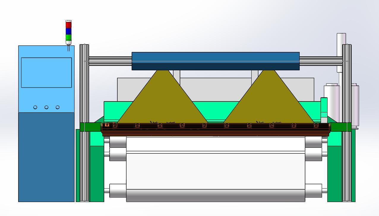
Option 1: fixed dual line-scan capture
Two high-resolution line-scan cameras and a line light are fixed on an extrusion frame, with a high-speed encoder synchronizing acquisition to material movement.
| Cameras | 2 × 8K or 4K line scan |
|---|---|
| Lenses | 55 mm or 35 mm |
| Lighting | Custom-length line light |
| Synchronization | 2500-line encoder |
| Compatible width | ≤ 3000 mm |
| Optical method | Surface reflection |
- Suited to fixed field-of-view coverage on continuously moving material.
- Inspection follows loom speed and targets broken yarn, oil stains, and related anomalies.
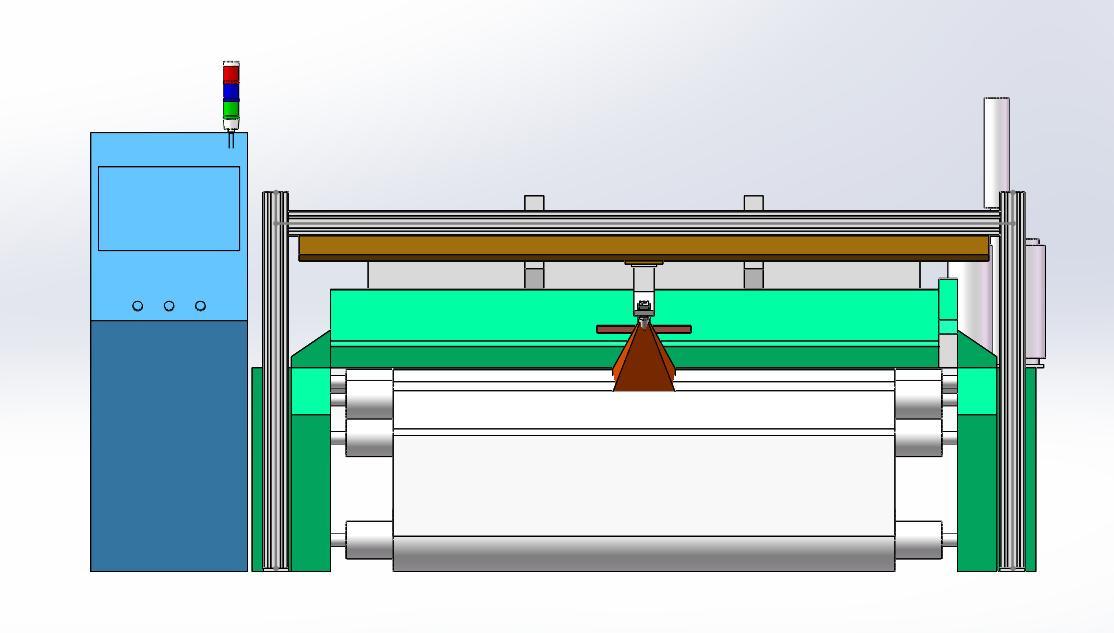
Option 2: moving area-camera capture
An area camera and bar light move on a linear stage to cover wider material and accommodate different machine structures.
| Camera | 1 × 5 MP or 2 MP area camera |
|---|---|
| Lens | 16 mm or 25 mm |
| Lighting | Custom-length bar light |
| Motion | Site-specific linear stage |
| Compatible width | ≤ 6000 mm |
| Optical method | Front light + backlight |
- Suited to very wide machines or structures that fixed cameras cannot fully cover.
- Travel path and loom speed require joint on-site evaluation.
Software & data
Defect images, statistics, and history in one operating loop
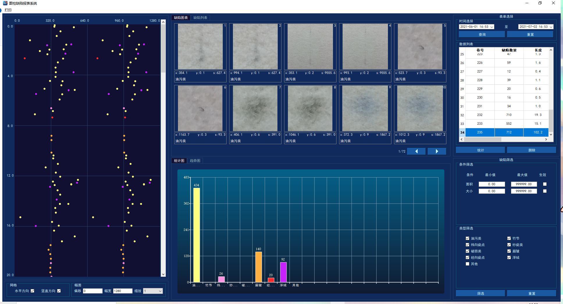
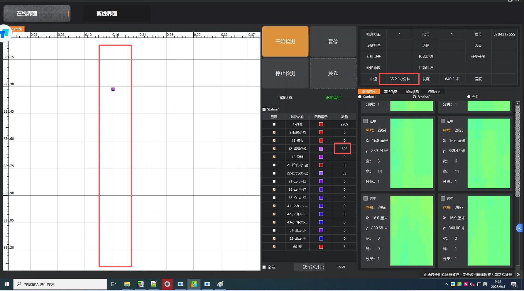
The software displays detected images and statistics in real time, with history search, quality reporting, cloud/local storage, and optional ERP data integration.
- Real-time defect image, position, and alarm state
- Statistics by defect type, count, and time
- Historical search and quality traceability
- Cloud storage with local database backup
- Optional integration with the customer's ERP system
Technical basis
- Computer Vision + Deep Learning Broken-yarn Inspection Equipment
- Zhongzhi Tuyou Product Brochure
These parameters are standard configurations and target values from the supplied textile solution. Final camera count, width, precision, and accuracy are confirmed against fabric samples, defect samples, loom structure, and site testing.
Send us fabric, defect samples, and loom parameters
We will compare line-scan and area-camera options and confirm width coverage, installation, and inspection limits.